PCB Surface Mount
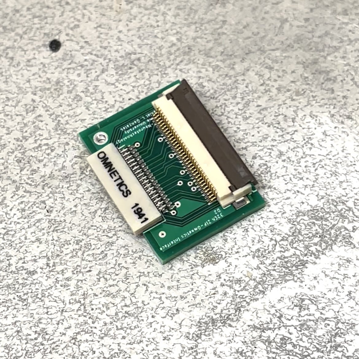
Whether your an engineer building new on-chip sensors or a neuroscientist who needs a customized connector for your experiment, it’s becoming increasingly common in research labs to design and piece together your own PCB (printed circuit board). In neuroscience specifically, as channel counts for in vivo electrophysiology are continuing to scale up; we rely more and more on small connectors with dozens miniscule leads. Check out this 32 channel Omnetics connector. Two rows of leads with a 0.5 mm pitch. It’s incredibly common in my field, but I never gave a second thought about how to mount it to a PCB…..until I had to do it myself!

The process is really quite simple and just takes some practice. The primary materials you require:
Your PCB. I’ve been using Eagle design software and Sunstone Circuits as a manufacturer and have no complaints.
Your components to mount on the PCB surface (connectors, op-amps, etc).
A solder stencil for your PCB (see below). This is basically a metal or plastic mask that allows you to put solder paste exactly where it needs to go on your PCB. One reason I like using Sunstone Circuits is that you can order the stencil when placing your PCB order.
Solder paste. For surface mount components, you don’t use solder in its more conventional wire-like form. Instead, you use a paste version. I suggest using Chip Quik SMD291AX paste.
Hotplate.

Now, I’ll walk you through it. If this is your first time, I strongly suggest using the cheapest component you have to practice with. These Omnetics connectors are $50 buck a pop! The other component, however, a ZIF (zero-insertion force) clip is only a few dollars.
Clean your PCB. A brief wipe with an IPA-soaked kimwipe will do. Not a terrible idea to clean off the leads of your connectors too. The oil from your fingers alone can effect the quality of the soldering process
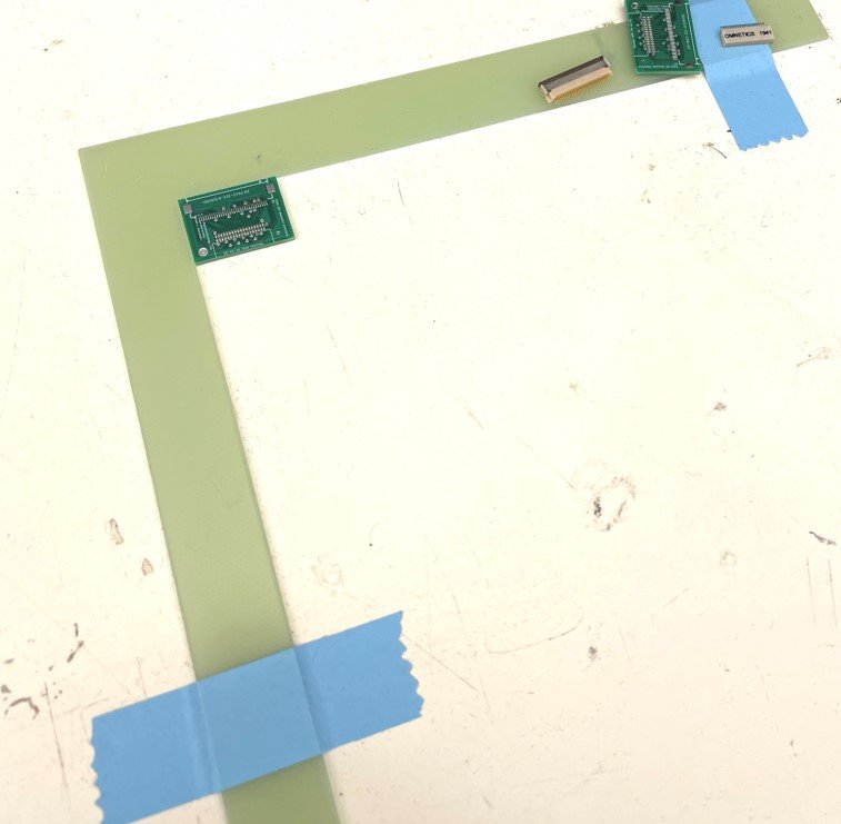
Secure your PCB to a flat surface. Again, this is a reason I like Sunstone Circuits. They send a convenient right-angle plastic piece for holding a PCB
Carefully align the stencil to the PCB. All of the PCB pads should be visible and perfectly match up.
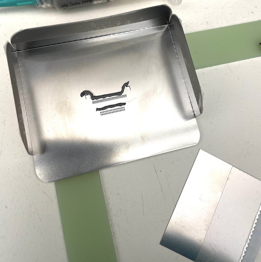
Holding the stencil in place, apply solder paste as shown..

Use a flat edge to scrape the solder paste downwards to fill the stencil holes. Press down hard and scrape the stencil clean. The paste should fill the holes. (Again, Sunstone Circuits will send you the perfect metal straight-edge for this step).
Remove the stencil carefully. Solder paste should remain only on the surface mount pads. It doesn’t have to be perfect. There can be a little overlap between pads.

Gently place your components. Align them as best you can. Tap down slightly so you can comfortably pick up the PCB with tweezers without the components moving and becoming misaligned

Carefully place the assembled PCB onto a hot plate at 350F. It’s best to have a metal plate instead of placing the PCB directly onto the hot plate surface (makes removal easier). Also note that online you’ll find hot air guns are commonly used for this step, but I’ve found a hotplate to be significantly more efficient and reliable.
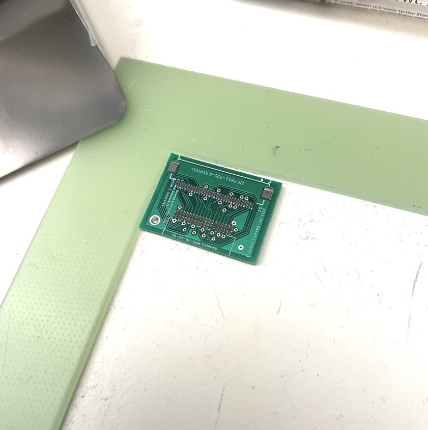
Here’s what the PCB looks like at the beginning of the bake. Note the dull gray color of the solder paste.

After a few minutes, you’ll start to see each solder pad melt and turn shiny silver. When all the pads are shiny, it’s finished. Carefully remove the chip from the hot plate. I find it easier to remove the whole metal plate, instead of trying to grab the PCB with tweezers.
Note: You have to be careful! While the solder is still hot and melted, large and fast movements can cause your surface components to shift or misalign during removal.
Allow to cool ~3-5min.
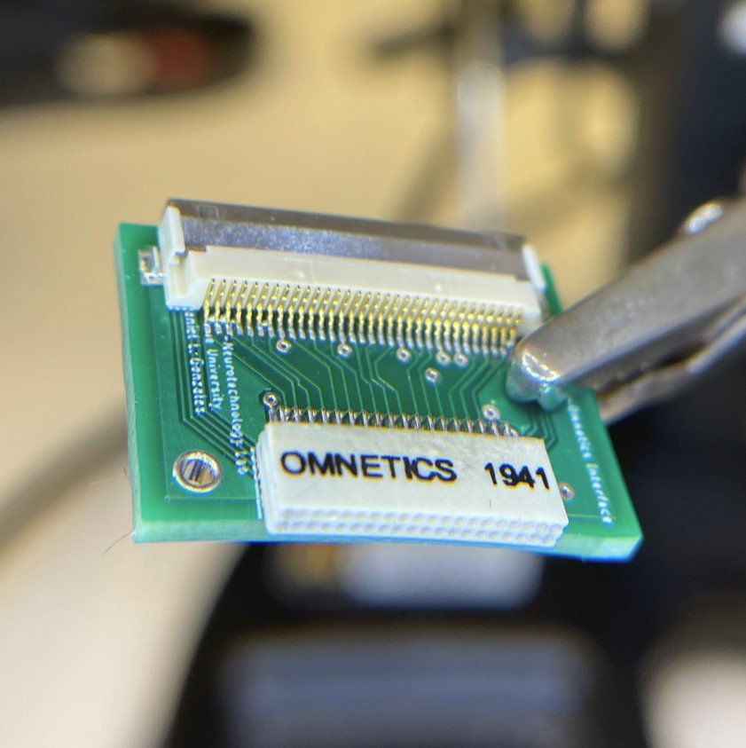
As the solder melts, it should pull all the the extra solder—and your components—neatly to the center of each pad. However, occasionally there is some crossover. On the left side of the chip here, you’ll see a few of the pads are shorted together by a small bridge of solder.
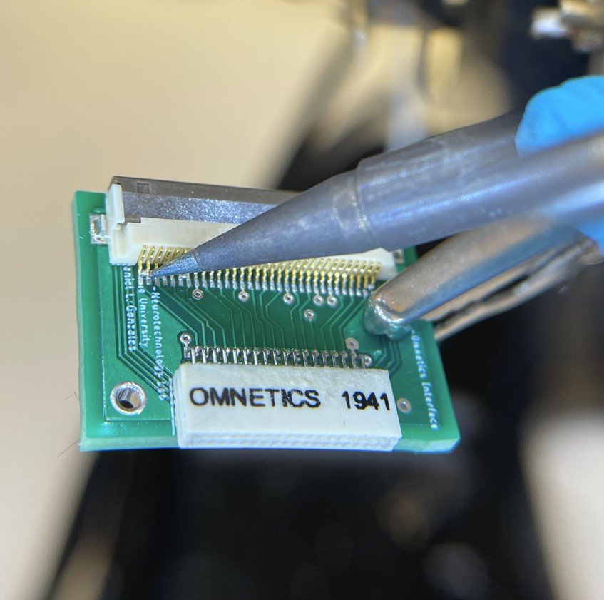
As a quick fix, I use a fine-tip soldering iron to “scrape” the extra solder out. If you really managed to get too much solder paste on there, you can try a de-solder copper mesh to remove the excess. But I usually find this unecessary.
There you have it. It’s really not bad. With practice, you’ll be able to knock one of these chips out in 15min. Ok. Time for another whiskey.
